SWATH ship design (Small Waterplane Area Twin Hull)

Cape Horn Engineering have proudly worked with Naiad Dynamics, ship motion control experts, on the CFD design optimisation for the stabilisation fins to improve the longitudinal stability of the Service Operation Vessel (SOV).

Recently launched at the CEMRE shipyard in Turkey, ‘Groene Wind’ is chartered to Siemens Gamesa Renewable Energy for the maintenance of offshore wind farms in Belgium. This is the first DP2, twin-hulled SOV in the world and the first to serve three different wind farm sites. The SWATH ship design provides a stable platform and large, broad decks for offshore crew activities services. The new vessel significantly improves safety, comfort and workability for wind farm technicians – even in the roughest sea conditions.

swath home 2

HULL DESIGN

The 60m twin-hull ship is designed to minimise the hull cross section area at the sea’s surface. The greatest benefit of this is that the waves have much less of an effect on the vessel, so it does not react as much to a heavy sea state. This improved seakeeping characteristics of the SWATH concept means there is a much more stable platform compared to a traditional monohull SOV, useful when approaching wind turbines and for safe crew transfers in waves. 

The bulk of the displacement is located beneath the waves, where it is less affected by wave action. The design of SWATH is considerably more complex due to the structural complexities inherent to the design. With high surface drag, yet low wave drag, the SWATH is less susceptible to wave motion, but more sensitive to payload, which affects the pitch and the draught.

FUEL EFFICIENCY

The vessels second generation Dynamic Positioning (DP2) technology means that the vessel can hold its position in rough seas but at the same time operate with lower fuel consumption when compared to traditional SOVs. An impressive fuel consumption reduction of up to 50% can be achieved compared to a monohull SOV, further reducing the cost of wind farm maintenance. In line with her green credentials, environmental considerations are integral to the vessel design and include a waste heat recovery system and a Clean Design notation.

CFD Analysis

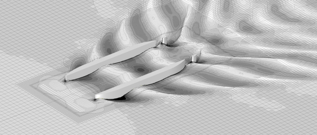
SWATH vessels are known for their inherent low longitudinal stability. They have the tendency of trimming bow down at maximum speed. To overcome this issue, the vessel was fitted with Naiad Dynamics’s stabilisation system – a pair of stabiliser fins mounted on the inner sides of both hulls, a short distance aft of the bow thrusters. The effects of the tunnels on the flow into the fins and thus the ability of them to perform properly and efficiently were a cause for concern.

CFD performance analysis were run for the whole vessel, including the rudders and fins, with the aim to achieve a better understanding of the correlation between rotating the fins, and regulating the SWATH’s trim. The analysis was performed over the range of operating speeds.

There were two main questions to be answered during the analysis of the SWATH; Firstly, are the installed fins capable of maintaining level trim while sailing at maximum speed, Secondly, which angle attacks give neutral lift for a range of boat speeds.

pasted image 25 e

Simulation Setup

The simulations were carried out following Cape Horn Engineering’s best practices at full scale with 2 Degrees-Of-Freedom (sinkage and trim), free surface deformation, viscous and turbulent flow. We use the best in market CFD code STAR-CCM+ by Siemens PLM. The simulations are run on a High Performance Computing (HPC) cluster, the mesh used had around 5 million cells so each simulation took about XXX hours to run until converged.

pasted image 27

Results for level trim at 12 knots

One of the investigations was to determine which fin angle would allow to achieve a 0 degree trim while sailing at 12 knots of boats speed.

The first step was to run a simulation of the model using the static centre of gravity with 12 knots of boat speed and the fin at 0 degree. This simulation showed the vessel to have a trim of -2 degrees, with approximately 20 kN of downward force generated by one fin. To reduce the bow down behaviour, the fin was rotated to a positive angle of attack (AoA) to produce more upward lift. Thus an iterative process was initiated, using linear interpolation to obtain the next best guess. This process reached a value for level trim having the fin at a moderate 7.8 deg.

Results for neutral lift

In the same manner as to find the angle of attack for level trim at 12 knots, an iterative method combined with linear interpolation was used to find the fin angles that produced zero lifting force at a rate of speeds. Run speeds of 8, 10 and 12 knots were completed first, from observations of these results, a better initial guess were used for the runs of 9 and 11 knots. The previous simulations with an AoA of zero were also considered.

While processing the simulations, linear and polynomial trends were observed for the Lift and the Trim at each speed. From these, it was possible to interpolate values for a more complete dataset. The aims of these interpolations being to provide a more detailed set of values, for Naiad Dynamic to be able to set-up the control system of the fins. A useful way of presenting the results is to link Lift generated with Trim, Fin angle and Boat speed.

pasted image 31

APPENDIX – Simulation Specifics

The CFD simulations are processed on a High Performance Computing (HPC) cluster running the latest version of the general purpose commercial code STAR-CCM+ by Siemens PLM. The code solves the Reynolds-Averaged Navier-Stokes Equations (RANSE), i.e taking into account viscosity. The k-omega SST turbulence model is applied with an all y+ treatment. An all y+ formulation switches from the traditional wall-function approach to a low Reynolds number approach with a blending function that is a function of the Reynolds number based on wall distance. The water-air interface is taken into account through the Volume Of Fluid modelling technique and the simulation is run in unsteady mode until a steady solution is reached and the forces and moments are converged to a tight tolerance of 0.1% over 200 time steps.

The CFD domain consists of a large box surrounding the vessel with the boundary conditions at least 2 or 3 boat lengths away from the vessel, so that no blockage effect is encountered. The symmetry of the simulation allows us to perform the analysis on half of the geometry to reduce computation effort.

The volume mesh has a resolution of around 5 million cells. They are composed of unstructured trimmed cells, i.e. predominantly hexahedral cells, with refinement prisms close to the body surfaces. The mesh also contains volume refinement zones. These are situated: around the fins to capture its motion relative to the hull; in the bow thruster tunnels to monitor the flow disruption in these areas and at the free surface to capture the waves generated by the SWATH around the hull and fins. These areas are where the flow gradients are the largest and a higher detailed representation of the geometry is required.

The effect of thrust of the propellers is considered in the trim attitude of the SWATH by applying a force in the direction of the propeller shaft. This force is obtained by considering its horizontal component equal to the computed drag of the vessel during the simulation. This method captures the main trim moment produced by the propulsion and is a good approximation if not enough information on the propeller is available.